-Excerpt from "Pinocchio" by Carlo Collodi.
This is an instrument of my own design and conception, as far as I know it is the only one of it's layout. The journey of it's creation is documented on my Facebook page, www.facebook.com/crazivn (search for the hashtag #realboy) so I will try to stick to the specifications of the instrument here and avoid anecdotes.


Pinocchio is currently on it's second chassis. The original was crudely made from old plywood simply to see if the layout was playable and work out any glaring issues with the system. The new chassis features a knee hook for seated playing, protruding edges to protect the plugs and DSUB connector, and slightly more streamlined wiring than the original.
For the keyboards I used a pair of Arturia Keystep MIDI controllers, chosen for their capability, rugged build quality and affordable price.
All signals are output from Pinocchio using a single 25-pin DSUB cable which leads to a rackmount breakout panel. Power is delivered into the upper end of the instrument from 6 AA batteries mounted in a cage on the strap. The cage is situated behind my shoulder.


In the battery picture you can see that the wiring is exposed on the back, I chose this method over a wire channel to retain the strength of the wooden chassis. Also I chose to use the existing plugs on the backs of the Keysteps rather than run wires into the bottom of the units and solder directly to the board contacts. This method is ugly, but will allow me to swap in a brand-new Keystep very quickly in the event of damage or malfunction. It's literally "plug and play".
Every output of each Keystep is transmitted to the breakout panel. Only the "MIDI in" functions are not used, as I saw no scenario where I would need them.

The "Sync out" of Keystep 2 (the Right-hand Keystep) is daisy-chained into the "Sync in" of Keystep 1. This allows me the choice of slaving the clock of Keystep 1 to the sequencer of Keystep 2, or having it independent by adjusting the dipswitches on Keystep 1.
The "Sync out" of Keystep 1 is sent to the breakout panel, and the "Sync in" of the breakout panel is received by Keystep 2.
The MIDI send of each Keystep is independent from the other, which allows for the greatest possibility of control over multiple synthesizers.
Here the breakout panel can be seen mounted in it's rack below the red Behringer Neutron. Jacks from left to right: DSUB In, Sustain Pedal inputs for each respective Keystep, Control Voltage (CV) outputs (Pitch, Gate and Modulation respectively) for each Keystep, Sync In, Sync Out, MIDI Out 1, MIDI Out 2.


Each MIDI jack also has a short MIDI cable extending from the rear of the jack (visible as the white cables in the lower pic), to accommodate rackmount synths that have the MIDI input on the rear (as is the case with the System-1m). This has the added advantage of allowing the front MIDI jacks to receive an input from any standard MIDI controller and essentially act as a feedthrough if Pinocchio is not being used.
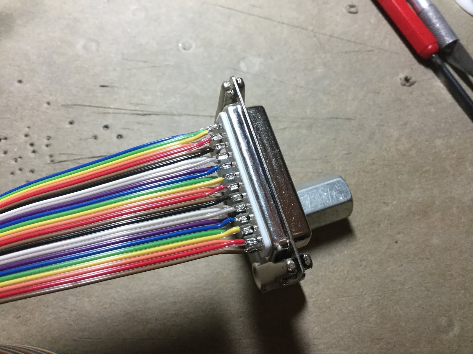
24 pins of the 25-pin DSUB cable are used to carry all the signals from Pinocchio to the breakout panel. Color-coded ribbon cable, situated in the small gap underneath the Keysteps, is used to distribute the appropriate signals to and from the DSUB connector on Pinocchio.
Here is a picture of the ribbon cable with the Keysteps unmounted.

To fasten the Keysteps securely, I used rivet nuts mounted in the steel chassis of each Keystep. Here is a picture taken during construction.

There are a total of five rivet nuts on each Keystep. I would have probably been fine using only four but Arturia has seen fit to give the Keystep five rubber feet, so I decided to follow their lead and situate a fifth rivet nut underneath the middle F key. There is plenty of clearance to accommodate a nut and short screw even with the key depressed.
Here is the pinout and construction notes I made for myself, to save a lot of multimeter time in case I need to service Pinocchio in the future. The colors correspond to the colors of the ribbon cable.

Control Possibilities:
Each Keystep is controlling a separate synth module via MIDI. However since each Keystep also outputs control voltage, there are interesting patch possibilities. For an example, the aftertouch on Keystep 1 is set to control the modulation on Synth 1. This frees up the modulation control on Keystep 1, which I can patch from the breakout panel into the "Pulse Width" parameter on Synth 2, thus allowing me to cross the controls over as I need them, to an extent.
There are also more complex possibilities which involve sending CV signals from the Pitch and Gate outputs to modify the sound in correspondence with the MIDI signals. At the time of this writing I haven't experimented with this, still learning the basics of the instrument.
I'll conclude the article for now, with some pictures of the construction process. Please feel free to email me or leave a comment here if you would like more information!
Thanks for reading!